
아두이노 led 여러개
아두이노 led 켜기
아두이노 led 깜빡이기
아두이노 led 연결
아두이노 led 순차점등
아두이노 led 버튼
아두이노 led 8개
아두이노 led rgb
주제에 대한 기사를 찾고 있습니까 “아두 이노 led“? 웹사이트에서 이 주제에 대한 전체 정보를 제공합니다 c2.castu.org 탐색에서: 292 사진을 다운로드할 수 있는 최고의 웹사이트. 바로 아래에서 이 주제에 대한 자세한 답변을 찾을 수 있습니다. 찾고 있는 주제를 더 잘 이해하려면 끝까지 읽으십시오.
이미지를 휴대폰에 다운로드하려면 이미지를 2초 동안 두 번 클릭한 다음 “이미지 다운로드” 다운로드를 선택하여 이미지를 다운로드할 수 있습니다.
컴퓨터에서 이미지를 다운로드하려면 이미지를 클릭한 다음 “다른 이름으로 이미지 저장”을 선택하여 다운로드할 수 있습니다.
Table of Contents
아두 이노 led 주제와 관련된 상위 146 이미지
주제 아두 이노 led 와 관련된 40 개의 이미지가 있습니다.
LED 제어 코드 작성 – 한 눈에 끝내는 아두이노 기초
아두이노(Arduino) 키트만 있다면 이미 갖추어진 실습환경에서 직접 코드를 작성하고 실행하며 아두이노의 기본을 다질 수 있습니다.
- Image source: edu.goorm.io
- Views: 17464
- Publish date: 9 minute ago
- Downloads: 45586
- Likes: 42
- Dislikes: 10

함수가 보입니다. digitalWrite 함수의 경우에는 해당 핀에 출력을 주는 것으로, 전류를 공급한다는 생각으로 접근하셔도 좋습니다. HIGH(= 5V 전류)와 LOW( = 0 V 전류 차단) 두 가지 상태를 출력할 수 있습니다.
함수는 핀 번호와 모드를 정해줌으로써, 특정 핀의 입력과 출력을 설정할 수 있습니다. 이번 예제의 경우에는 13 번 핀을 이용하고 출력이기 때문에
오른쪽 에디터의 주어진 코드가 의미하는 것은 13번 LED를 1초 간격으로 켜고, 끄고를 반복하는 코드입니다.
아두이노 예제 1. LED 깜빡이기 – 코딩런
LED(발광 다이오드)LED는 전기 에너지를 빛 에너지로 변환한 발광 다이오드이다. LED는 일반적으로 2개의 전극단자로 구성되어 있는데, 긴 단자쪽이 +(애노드 ANODE), 짧은 단자쪽이 -(캐소드 CATHODE)라고 한다. 따라서 각 단자마다 극성을 가지고 있고, 긴 단자(애노드)에 +를 짧은 단자(캐소드)에 -전극을 연결하면 된다.전류가 지나치게 흐를경우 LED가 파손되거나 고장이 발생할 수 있으므로 저항을 달아주는것이 좋다.저항을 고를 때에는 옴의법칙을 이용하여 저항을 선정한다. 옴의법칙V(전압)=I(전류)*R(저항)R(저항)=V(전압)/I(전류)I(전류)=V(전압)/R(저항)우리는 LED를 보호하기 위한 저항을 달아야 하므로, R = V / I를 사용하면, LED의 필요전압은 2V이며, 소모전..
- Image source: codingrun.com
- Views: 64882
- Publish date: 15 hours ago
- Downloads: 4075
- Likes: 4295
- Dislikes: 9

LED는 전기 에너지를 빛 에너지로 변환한 발광 다이오드이다. LED는 일반적으로 2개의 전극단자로 구성되어 있는데, 긴 단자쪽이 +(애노드 ANODE), 짧은 단자쪽이 -(캐소드 CATHODE)라고 한다. 따라서 각 단자마다 극성을 가지고 있고, 긴 단자(애노드)에 +를 짧은 단자(캐소드)에 -전극을 연결하면 된다.
우리는 LED를 보호하기 위한 저항을 달아야 하므로, R = V / I를 사용하면, LED의 필요전압은 2V이며, 소모전류는 10mA이다.
300Ω 저항을 사용하면 되고, 300Ω 저항이 없을 경우 근사치 저항을 사용하시면 된다. 필자는 330Ω 저항을 사용하였다.
아두이노 예제 1. LED 깜빡이기 – 코딩런
LED(발광 다이오드)LED는 전기 에너지를 빛 에너지로 변환한 발광 다이오드이다. LED는 일반적으로 2개의 전극단자로 구성되어 있는데, 긴 단자쪽이 +(애노드 ANODE), 짧은 단자쪽이 -(캐소드 CATHODE)라고 한다. 따라서 각 단자마다 극성을 가지고 있고, 긴 단자(애노드)에 +를 짧은 단자(캐소드)에 -전극을 연결하면 된다.전류가 지나치게 흐를경우 LED가 파손되거나 고장이 발생할 수 있으므로 저항을 달아주는것이 좋다.저항을 고를 때에는 옴의법칙을 이용하여 저항을 선정한다. 옴의법칙V(전압)=I(전류)*R(저항)R(저항)=V(전압)/I(전류)I(전류)=V(전압)/R(저항)우리는 LED를 보호하기 위한 저항을 달아야 하므로, R = V / I를 사용하면, LED의 필요전압은 2V이며, 소모전..
- Image source: codingrun.com
- Views: 32088
- Publish date: 24 hours ago
- Downloads: 32304
- Likes: 7626
- Dislikes: 1

LED는 전기 에너지를 빛 에너지로 변환한 발광 다이오드이다. LED는 일반적으로 2개의 전극단자로 구성되어 있는데, 긴 단자쪽이 +(애노드 ANODE), 짧은 단자쪽이 -(캐소드 CATHODE)라고 한다. 따라서 각 단자마다 극성을 가지고 있고, 긴 단자(애노드)에 +를 짧은 단자(캐소드)에 -전극을 연결하면 된다.
우리는 LED를 보호하기 위한 저항을 달아야 하므로, R = V / I를 사용하면, LED의 필요전압은 2V이며, 소모전류는 10mA이다.
300Ω 저항을 사용하면 되고, 300Ω 저항이 없을 경우 근사치 저항을 사용하시면 된다. 필자는 330Ω 저항을 사용하였다.
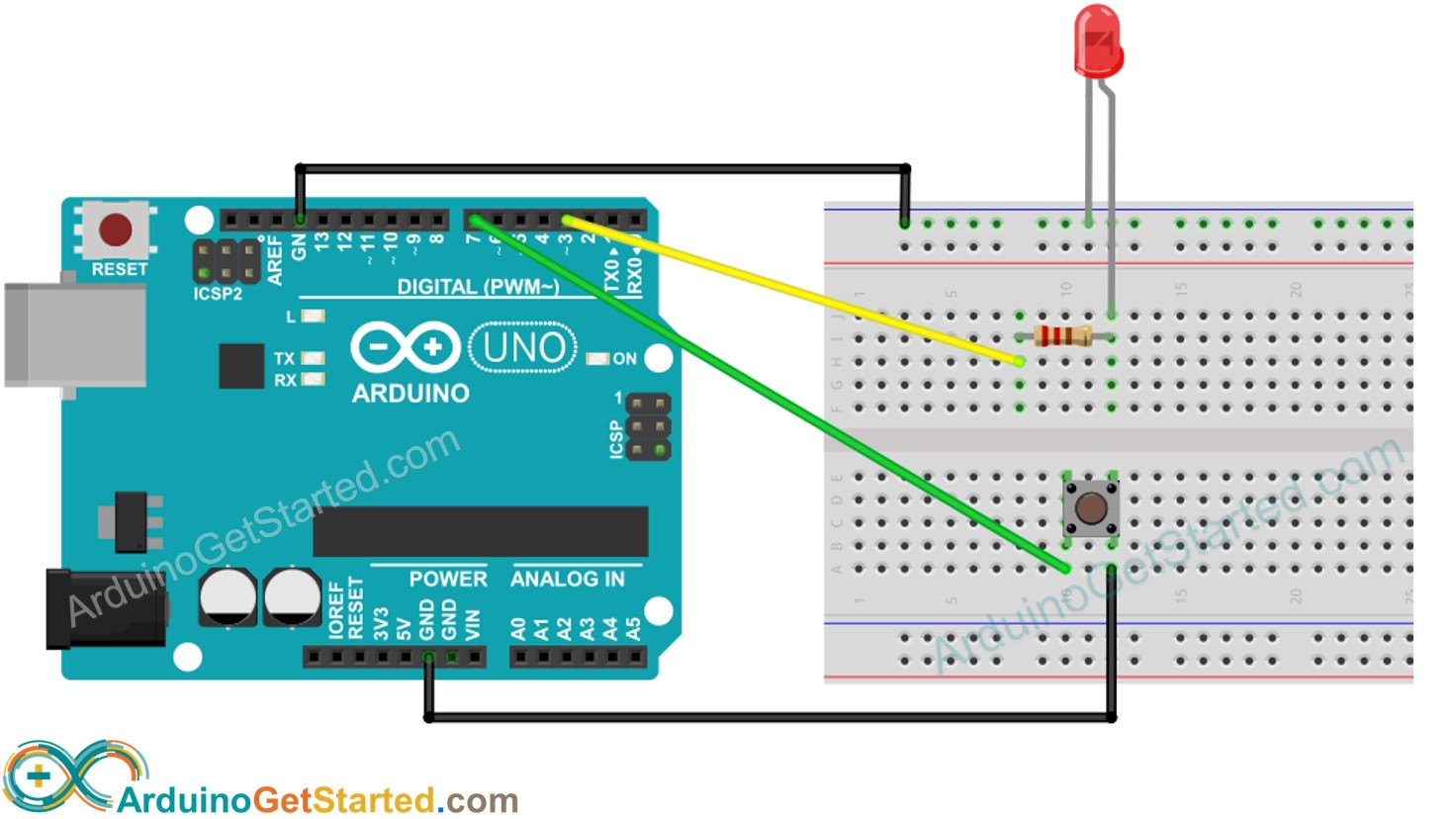
Arduino – Button Toggle LED | Arduino Tutorial
Learn how to use button to toggle LED. The detail instruction, code, wiring diagram, video tutorial, line-by-line code explanation are provided to help you quickly get started with Arduino. Find this and other Arduino tutorials on ArduinoGetStarted.com.
- Image source: arduinogetstarted.com
- Views: 83237
- Publish date: 19 hours ago
- Downloads: 57829
- Likes: 5737
- Dislikes: 10
ArduinoGetStarted.com is a participant in the Amazon Services LLC Associates Program, an affiliate advertising program designed to provide a means for sites to earn advertising fees by advertising and linking to Amazon.com, Amazon.it, Amazon.fr, Amazon.co.uk, Amazon.ca, Amazon.de, Amazon.es and Amazon.co.jp
You can share the link of this tutorial anywhere. Howerver, please do not copy the content to share on other websites. We took a lot of time and effort to create the content of this tutorial, please respect our work!
, We have learned how to turn on the LED if the button is pressed, and turn off LED if the button is released. In this tutorial, We are going to learn how to toggle LED each time button is pressed.
스위치로 LED 제어하기 – 한 눈에 끝내는 아두이노 기초
아두이노(Arduino) 키트만 있다면 이미 갖추어진 실습환경에서 직접 코드를 작성하고 실행하며 아두이노의 기본을 다질 수 있습니다.
- Image source: edu.goorm.io
- Views: 6177
- Publish date: 31 minute ago
- Downloads: 28715
- Likes: 9839
- Dislikes: 4

조건문을 사용하여 buttonPin의 값을 digital 방식으로 읽어 LOW 상태일 때 LED를 켜고, HIGH (기본상태) 일 때 LED를 끄는 동작을 하도록 만들었습니다.
스위치 두 개를 연결하여 하나는 LED를 켜는 기능, 다른 하나는 LED를 끄는 기능을 만들어 보세요!
스위치 하나를 연결하여 스위치를 누르는 동안 LED를 켜는 코드입니다.
[강좌] 5. 아두이노 내장 LED 제어하기 ~ 메이드올
- Image source: gucciheon.blogspot.com
- Views: 93548
- Publish date: 18 minute ago
- Downloads: 43169
- Likes: 5340
- Dislikes: 1
![강좌] 5. 아두이노 내장 Led 제어하기 ~ 메이드올](https://1.bp.blogspot.com/-2rER7hyhleQ/Wksv-BtaHZI/AAAAAAAAAg8/VHJmyx31lpsr-BY6vZvSk6ifVkko9jacQCLcBGAs/s1600/1.png)
대부분의 아두이노는 제어가 가능한 LED가 내장되어 있습니다. UNO 보드 MEGA보드, ZERO보드에 13번 디지털 핀으로 내장되어 있습니다. MKR1000보드의 경우 6번 핀에 연결되어 있습니다.
위 코드에서는 LED에 불을 키고 끄기 위해 LED_BUILTIN을 UNO보드를 사용한다면 13으로 바꿔줍니다. 전압의 상태를 0과 1 또는 LOW와 HIGH로 조절합니다.
LED_BUILTIN 이라는 핀을 출력모드로 정하고, 반복구문에서 LED_BUILTIN 핀에 전압을 높여주고 1초간 쉬었다가 전압을 낮춰주고 1초간 쉬는 작업을 반복합니다.
[아두이노 LED] Arduino LED 깜빡이기_EP2
◎ 아두이노 LED 제어하기 아두이노를 활용하여 LED 제어하기 1. 1초간 아두이노 깜빡이기 ○ 사용 부품 1) 아두이노 UNO 2) LED 3) 220옴 저항 ○ 회로 연결 ○ 적용 코드 void setup() { pinMode(13,OUTPUT); //13번 핀모드 선언 } void loop() { digitalWrite(13,HIGH); // 13번 핀 5V 출력 delay(1000);// 1초 대기 digitalWrite(13,LOW);// 13번 핀 0V 출력 delay(1000);// 1초 대기 } ○ 작동 영상 2. 1초간 LED 2개 깜빡이기 ○ 사용 부품 1) 아두이노 UNO 2) LED 3) 220옴 저항 ○ 회로 연결 ○ 적용 코드 void setup() { pinMode(13,OU..
- Image source: kgu0724.tistory.com
- Views: 15938
- Publish date: 8 hours ago
- Downloads: 77469
- Likes: 973
- Dislikes: 10
![아두이노 Led] Arduino Led 깜빡이기_Ep2](https://blog.kakaocdn.net/dn/TK2KV/btqBGe2SAjz/9dZRHBBKKuTijo28O2t7H1/img.jpg)
digitalWrite(13,HIGH); // 13번 핀 5V 출력
digitalWrite(13,LOW); // 13번 핀 0V 출력
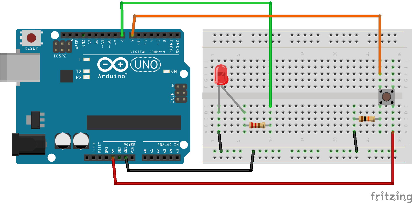
[아두이노] HC-06 블루투스 이름 변경 (AT Command)[아두이노 연재] 아두이노 GPIO 사용하기 – LED와 버튼
지난주부터 아두이노 연재를 시작했지요. 지난번에 이어서 가장 간단한 LED와 버튼을 이야기 해보려고 합니다. 오늘 필요한 재료는 LED 두 개와 버튼 (사진으로는 두개인데, 그냥 하나) 330옴 저항 두개, 1k옴 저항 하나, 그리고 점핑 와이어가 있으면 됩니다. 그리고, 지난 시간에서도 사용했던 아두이노 우노 보드와 케이블, 그리고 약간 생소한 브레드보드(일명 빵판)가 있으면 됩니다. 이게 브레드보드입니다. 이름처럼 빵(^^)스럽게 생기진 않았지만, 아주 유용한 아이입니다. 전기쪽에서 부품을 연결하려면 납땜이라는 것을 해야할텐데, 이 보드를 사용하면 그렇게 하지 않아도 됩니다. 간단하게 부품을 배치하고 연결해서 테스트해볼 수 있는 거죠. 그리고 나서 테스트가 끝나면 다시 부품을 재활용할 수 있습니다. ..
- Image source: pinkwink.kr
- Views: 51355
- Publish date: 45 minute ago
- Downloads: 24193
- Likes: 6891
- Dislikes: 6
![아두이노 연재] 아두이노 Gpio 사용하기 - Led와 버튼](https://t1.daumcdn.net/cfile/tistory/99A70B465D106E032C)
그리고, 이렇게 코드를 작성합니다. 위 코드는 전혀 어렵지 않습니다. 그저 RED와 GREEN LED를 각각 3번 5번에 연결한 것을 변수로 저장해 두고, setup() 함수에서 출력(OUTPUT)이라고 모드를 설정합니다. 그리고, digitalWrite 명령으로 HIGH를 전송해서 켜보는 것이지요. 그러면 저 코드를 업로드하면 그냥 켜집니다.
이제 저항을 연결합니다. 두 LED 모두 GND는 검은선으로 연결했고, 그 다음 + 방향의 선에 저항을 330옴을 연결합니다. 응? 왜 330옴이냐구요. 5볼트에 330옴을 연결하면, 옴의 범칙에 의해 아마 10~20mA정도가 만들어집니다. 저런 종류의 LED를 구동하기 위해 필요한 전류인거죠. 뭐 아무튼, 그래서 저항을 저렇게 연결합니다.
버튼은 위 그림처럼 연결을 많이 합니다. 버튼을 누르기 전에는 버튼으로는 전기가 흐리지 못합니다. 그러면 + 신호는 그냥 그림 오른쪽 신호라고 표기된 곳으로 지나가서 HIGH가 됩니다. 버튼을 누르면 버튼 방향으로 흘러서 신호라고 표기된 곳 입장에서는 LOW가 됩니다. 즉. 버튼을 누르면 LOW, 안누르면 HIGH입니다.
아두이노 기초 – 삼색 LED 사용하기 – YouTube
아두이노 기초삼색 LED 사용하기
- Image source: m.youtube.com
- Views: 97015
- Publish date: 2 hours ago
- Downloads: 26825
- Likes: 7889
- Dislikes: 4

Cách YouTube hoạt động
Liên hệ với chúng tôi
Chính sách và an toàn
Fading a LED | Arduino Documentation | Arduino Documentation
- Image source: www.arduino.cc
- Views: 24760
- Publish date: 25 minute ago
- Downloads: 24852
- Likes: 2421
- Dislikes: 8
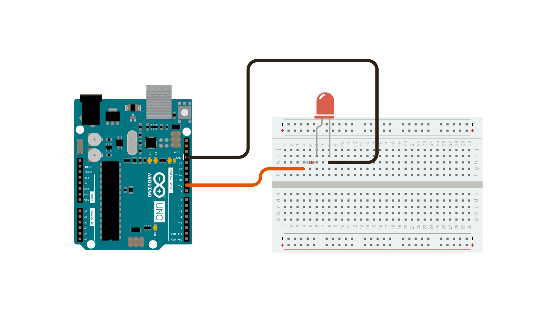
In order to fade your LED off and on, gradually increase your PWM value from 0 (all the way off) to 255 (all the way on), and then back to 0 once again to complete the cycle. In the sketch below, the PWM value is set using a variable called
can change the PWM value very fast, so the delay at the end of the sketch controls the speed of the fade. Try changing the value of the delay and see how it changes the fading effect.
function that you will be using in the main loop of your code requires two arguments: One telling the function which pin to write to, and one indicating what
아두이노 – 무드등 예제, RGB LED 제어 :: postpop
아두이노는 analogWrite() 함수를 통해 간단하게 RGB LED를 제어할 수 있다. 여기에 앞선 글에서 다루었던 버튼과 터치 센서를 달고 원하는 색상과 밝기를 설정하고, 또한 정해진 시간 간격으로 랜덤 한 색상이 변경되고 색상이 변경될 때 자연스럽게 변경되도록 코드를 짜 보자. 일반 버튼 1. RGB LED ON / 밝기 조절 모드 진입 2. 색상 설정 모드 진입 – 기본 LED ON 3. 멀티 색상 패턴 모드 – 기본 LED OFF 4. RGB LED OFF 터치버튼 1. 밝기 조절 모드에서 RGB LED 밝기 제어 2. 색상 설정 모드에서 정해진 색상을 순서대로 변경 3. 멀티 색상 패턴 모드에서 아래 패턴 선택 – 정해진 시간 간격에 따라 정해진 색상 변경 – 정해진 시간 간격에 따라 무지개..
- Image source: postpop.tistory.com
- Views: 103331
- Publish date: 4 minute ago
- Downloads: 60769
- Likes: 6809
- Dislikes: 6

상기 사이트에는 HSV에 대해 설명하고 있으며, 색상(Hue) 값은 0 ~ 360도 원형 값이고, 명도(Value)는 0~100인 퍼센트 값으로 표시되며, 채도(Saturation)를 조절하여 파스텔 톤의 색상을 만들 수는 있으나 빛의 조합으로 만들어지는 RGB LED의 색상에서는 흰색의 밝기 변화와 비슷하게 느껴질 거라고 언급하고 있다. 더불어 아래 그림처럼 무지개 색 변화를 표현하기 위한 RGB Sine wave 변화와 HSV 파의 변화를 비교하여 설명하고 있다. 또한, 이 표에 표시된 3가지 색상 표현방식 “Regular HSV, Power-conscious HSV, Sine wave”들의 RGB 변동 값을 배열로 만드는 코드를 제시하고 있으며(RGB 각 항목의 변동 패턴은 동일하다, 다만 위상차가 있다. – 각 색상 표현 방식은 한 개의 변동 값 배열만 필요함), 이 변동 값이 포함된 배열을 이용하여 무지개 색 변화를 표현하는 코드도 제시하고 있다.
RGB 각각의 색상 값으로 0 ~ 255의 값이 사용되는데 조합된 색상의 관점에서 보면 이는 255를 최댓값으로 하는 비율 값이다. 만약 R의 값이 변경되었을 때 다른 G나 B값이 R값의 변경된 비율만큼 변경된다면(RGB 각각의 색상 비율이 같다면) 색상은 그대로인 상태가 된다. 예를 들어 “R:255, G:255 B:255″로 조합된 색상은 흰색이다. “R:100, G:100 B:100″로 조합된 색상 또한 흰색이다. 단지 밝기가 변경되는 것이다. 이렇게 원하는 색상의 밝기만 조절하고자 한다면 RGB 각각의 색상 값을 같은 값으로 나누어 주게 되면 되는데, 나누는 방법으로 시프트 연산자를 사용하겠다. 한 칸씩 우측으로 이동할 때마다 2, 4, 6, 8로 나누는 것과 같다. 자세한 사항은 “시프트 연산자”를 검색하면 살펴볼 수 있다.
기본 색상에 chocolate 색상만 추가한 색상표이다. 유의할 점은 색상표의 색상이 실제 RGB LED에 그대로 표현되지 않는다는 것이다. 색상표는 물감이나 인쇄된 색상에서 반사된 빛을 눈이 인지하는 색상을 도식화해놓은 것이고 RGB LED에 의해 표현되는 색상은 빨강, 녹색, 파랑 빛의 조합에 의해 만들어지는 색상이라 정확하게 일치하지 않게 된다. 예를 들어 은색, 연회색, 짙은 회색 등은 빛의 조합으로는 명확하게 표현할 수 없는 색이다. 이러한 색들은 (특히, 어두운 계열) 밝기의 차이로만 느껴지게 된다.
Arduino – Turn LED ON and OFF With Button – The Robotics Back-End
Arduino Tutorial: Learn how to make a circuit with a LED and push button, and how to turn the led on and of with the button.
- Image source: roboticsbackend.com
- Views: 92473
- Publish date: 6 hours ago
- Downloads: 240
- Likes: 3759
- Dislikes: 1
This website uses cookies to improve your experience while you navigate through the website. Out of these, the cookies that are categorized as necessary are stored on your browser as they are essential for the working of basic functionalities of the website. We also use third-party cookies that help us analyze and understand how you use this website. These cookies will be stored in your browser only with your consent. You also have the option to opt-out of these cookies. But opting out of some of these cookies may affect your browsing experience.
This is because the button is physically bouncing when you press it. Thus, many false positives will be interpreted by the Arduino. What you can do to prevent that is to add a debounce delay in your code. For example, you can decide that when the program detects a change in the button’s state, it will wait 50 milliseconds before considering another change viable.
Once the debounce delay has been passed, then we can do what we did before. And don’t forget to update the starting point for the “debounce timer” just after you detect a change in the button’s state. So, the next time the program enters the loop, it will wait for 50 milliseconds (or the value you’ve chosen) to detect new changes in the button’s state.
RGB LED with Arduino Tutorial – Makerguides.com
Learn the basics of using an RGB LED in Arduino, so you can create your own colors with the help of potentiometers.
- Image source: www.makerguides.com
- Views: 85830
- Publish date: 57 minute ago
- Downloads: 74624
- Likes: 265
- Dislikes: 5
How bright an LED shines is controlled by how much current flows through it, but we cannot directly control the current as the Arduino Uno lacks fully analog outputs, to control its brightness we’ll be using Pulse Width Modulation (PWM).
In this step I use the PWM outputs of the Arduino to light up the red, green and blue pins on the RGB led with the integer values obtained from the potentiometers, you just need to specify the pin and the number between 0 and 255.
Makerguides.com is a participant in the Amazon Services LLC Associates Program, an affiliate advertising program designed to provide a means for sites to earn advertising fees by advertising and linking to products on Amazon.com.
아두이노로 LED를 켜보자! (디지털핀, 아날로그핀)
오늘의 회로도는 LED를 켜는 가장 기본이 되는 명령어에 대해서 알아볼까 한다. [LED를 켜기 위한 사전 지식] 우선 아두이노의 기본적인 정보부터 탐색해볼까 한다. POWER: 전원과 관련된 부분이다. 3.3V, 5V가 (+) 역할을 GND가 (-) 역할을 한다 ANALOG IN: 아날로그 신호를 입력(IN) 받는 단자 DIGITAL: 디지털 신호를 입출력 받을 수 있는 단자 (~PWM) : Pulse Width Modulation 펄스 폭 변조. 역할은 아래에 적겠음 [아날로그 신호와 디지털 신호] 1. 디지털 신호: 전기 신호의 일종으로 0(LOW)과 1(HIGH)로 표현된다. 아두이노의 디지털 단자는 5v의 출력을 내므로 LOW=0v=없음 HIGH=5v=있음 으로 기억해도 좋다. 아두이노의 디지털..
- Image source: studylee00.tistory.com
- Views: 6742
- Publish date: 1 hours ago
- Downloads: 34479
- Likes: 346
- Dislikes: 5

2020/03/07 – [공부하는 이땡땡/건담을 만들어보자] – 건담에 넣을 LED 연결방법 (LED 병렬 연결, 저항계산법, 강하전압)
이제 새롭게 i=10이 되고 255보다 작으므로 아날로그 신호 10 출력. 0.1초 대기. 그리고 i=20이 된다.
언젠가 i=250이 되고 255보다 작으므로 아날로그 신호 250 출력. 0.1초 대기. 그리고 i=260이 된다.
Arduino Breathing LED Functions — Maker Portal
In this tutorial – an Arduino board will be used in conjunction with an RGB LED to investigate several ways of replicating the breathing LED effect. Using the equation for a triangular wave, circular wave, and Gaussian wave, a breathing LED will be constructed. The amount of code needed for the simp
- Image source: makersportal.com
- Views: 32967
- Publish date: 54 minute ago
- Downloads: 33386
- Likes: 3511
- Dislikes: 2
A breathing LED is a phenomenon that mimics the inhale and exhale of a lung with light instead of air. Breathing LEDs can be found in many electronics, and are often a sign of functionality to some degree. In this tutorial, a few functions were proposed that are able to replicate the breathing phenomenon. The triangle, circular, and gaussian waves were all presented and demonstrated for an Arduino board and RGB LED. Each function uses a loop to cycle through darkness and brightness, giving the illusion of a ‘breathing’ LED. This tutorial is merely an introduction to modulating LED brightness with different mathematical functions. The goal was to create an array of methods for creating the breathing phenomenon, and this was done with the three aforementioned functions. The Gaussian wave proves to be both the most versatile and most natural of the functions, however, the simplicity of the triangle wave makes it a great (and likely common) selection for creating a breathing LED.
A “breathing LED” is a phenomenon where an LED’s brightness smoothly changes from dark to bright and back to dark, continuing to do so and giving the illusion of an LED “breathing.” This phenomenon is similar to a lung breathing in and out. There are several ways of achieving the breathing LED phenomenon, by manual loops or mathematical functions. The trick is to create a loop that goes from peak to minimum, or using a function that does this within its bounds. In this tutorial, an Arduino board will be used in conjunction with an LED to investigate several ways of replicating the breathing LED effect, which will make creating a breathing LED a simple procedure – regardless of the application. The amount of code needed for the simplest breathing LED is as little as two lines of code, while some more complex breathing functions grow in difficulty from there.
A lot of Arduino code is single-sided, meaning that many of the loops range from zero to some number. This is because many of the functions of a microcontroller start with zero and increase positively and are related to iterables. In this section, functions are explored that have a peak at their midpoint and maintain smoothness throughout the function. These functions will create the ‘breathing’ of the LED by starting with minimal brightness, peaking in brightness, and going back to minimal brightness – all without any abrupt changes. This is similar to the intake and exhale of air into a lung. The list of five functions explored in this tutorial are given below:
LED Strip SMD 5050 – LEDs and Multiplexing – Arduino Forum
Hi! I am attempting to control a 12V RGB LED strip (SMD 5050) from an Arduino Uno (and Nano), and have set up the following breadboard. When I power on the circuit with a 12v power adaptor, the led turns on to white, but doesn't execute my sketch, which should fade from a color to another. As I'm pretty new to this, have I made a blatant mistake? (Probably, as I seem to have fried my MacBook Air when I connected to both USB and power at the same time…) Any feedback would be greatly apprecia…
- Image source: forum.arduino.cc
- Views: 63580
- Publish date: 9 hours ago
- Downloads: 100338
- Likes: 7092
- Dislikes: 2

Stp16nf06l would be suitable. I say that because I have memorized the part number! There are probably hundreds to choose from. What you are looking for is “n-channel” and “logic-level” and probably in a “to-220” package. Most of them will have a higher maximum voltage and current than you need, so don’t worry so much about those figures.
I am attempting to control a 12V RGB LED strip (SMD 5050) from an Arduino Uno (and Nano), and have set up the following breadboard. When I power on the circuit with a 12v power adaptor, the led turns on to white, but doesn’t execute my sketch, which should fade from a color to another.
I don’t see a difference. It’s still the case that all the current flowing back to the PSU connector through the ground line is still passing through the Uno board, albeit between neighbouring pins.
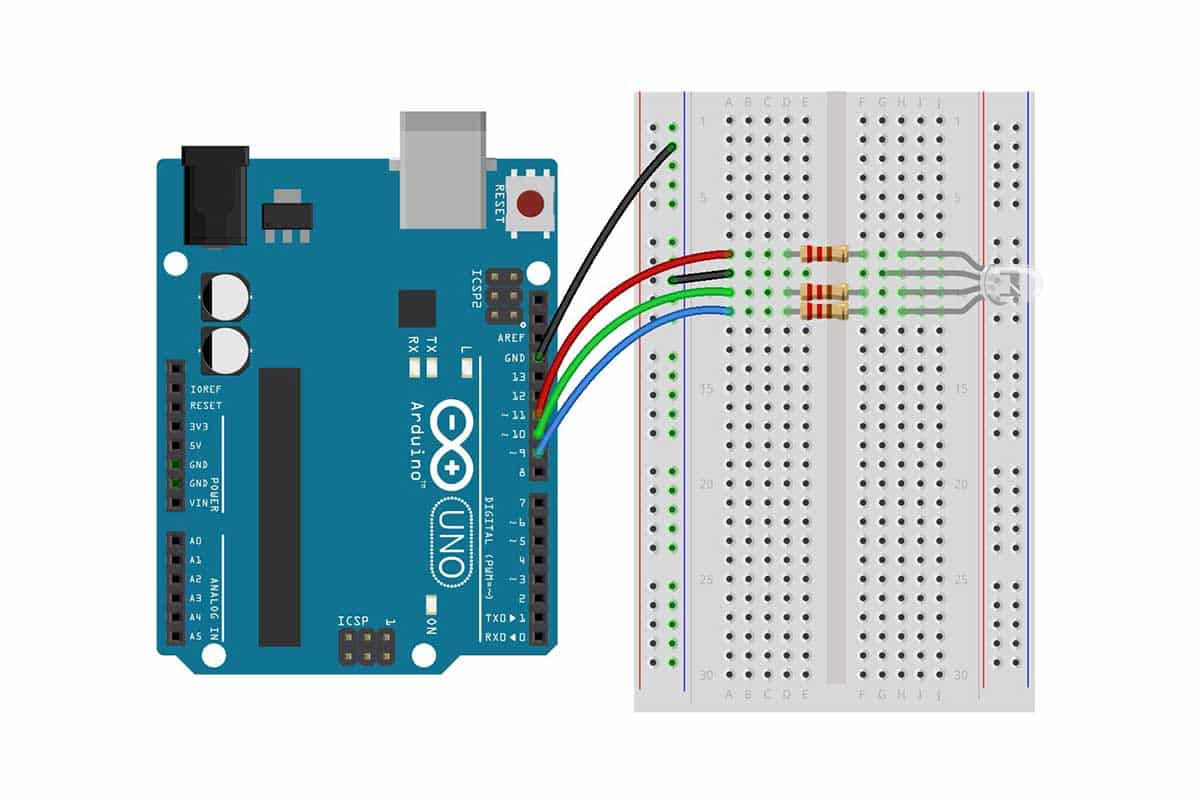
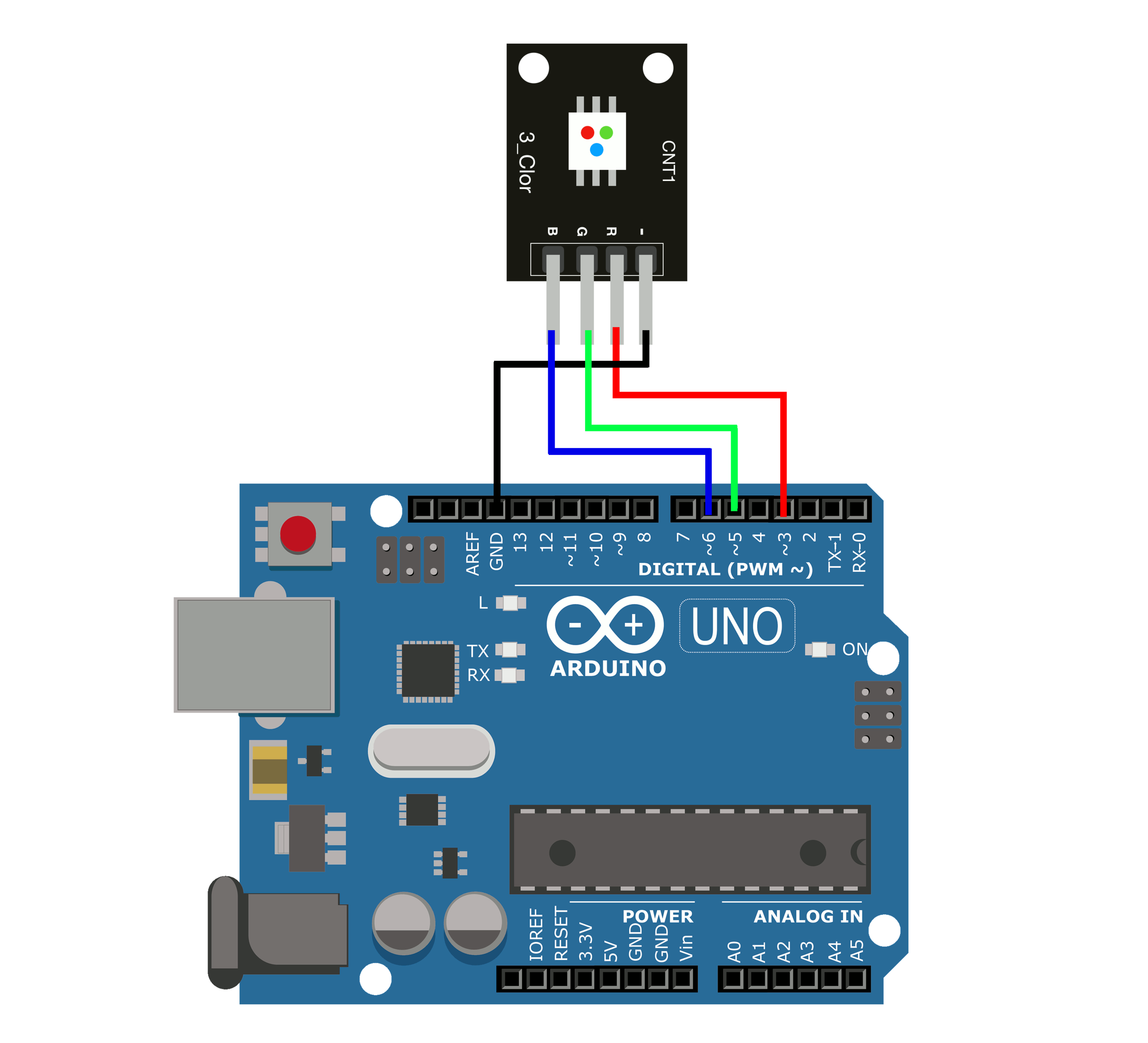
틴커캐드 아두이노 3색 RGB LED 제어하기
이전 블로그에서 브레드보드와 LED 페이드 인/페이드 아웃 (PWM) 제어하는 방법을 알아보았습니다. https://iot-lab.tistory.com/175 틴커캐드 아두이노 LED 페이드 인/페이드 아웃 제어하기(PWM 제어, 오실로스코프, 멀티미터) 이전 블로그에서 브레드보드와 3가지 색의 LED를 제어하는 방법을 알아보았습니다. https://iot-lab.tistory.com/83 틴커캐드 아두이노 브레드보드와 LED 3개 제어하기 오늘은 틴커캐드 아두이노 시뮬레이 iot-lab.tistory.com 사전 지식 3색 LED (RGB LED) 한쪽 방향으로 전류가 흐르도록 하는 반도체 소자를 다이오드라고 합니다. 그중 전기 에너지를 빛으로 변환하는 것을 발광 다이오드(LED)라고 합니다. LED(..
- Image source: iot-lab.tistory.com
- Views: 41209
- Publish date: 25 minute ago
- Downloads: 83625
- Likes: 639
- Dislikes: 5
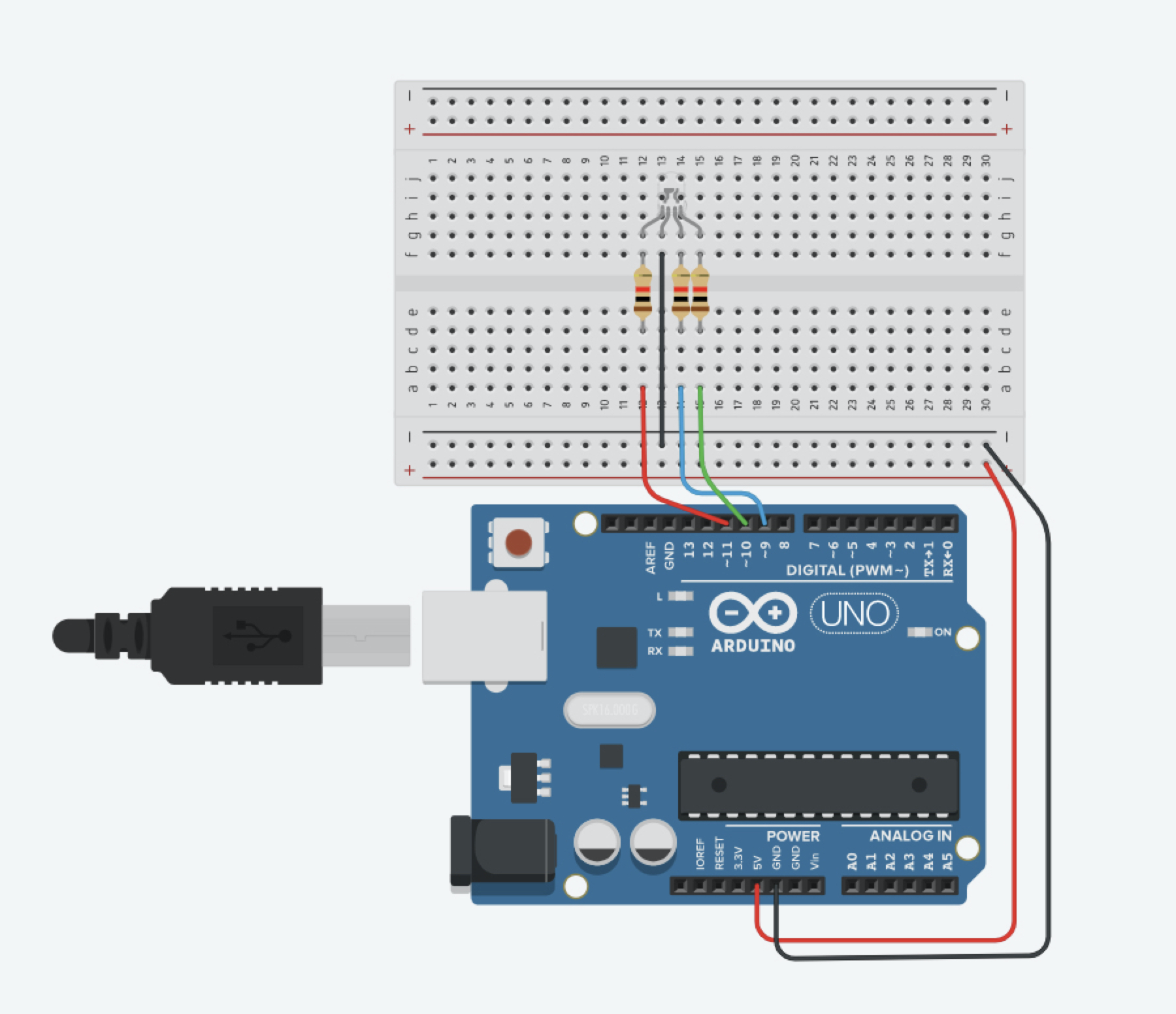
4. 데이터선을 각각 아두이노의 11 번핀(LED 빨간색), 10 번핀(LED 초록색), 9 번핀(파란색)을 아래 그림과 같이 연결 (전선은 각 색에 맞춰 연결하면 구별하기 좋음)
그중 전기 에너지를 빛으로 변환하는 것을 발광 다이오드(LED)라고 합니다. LED(Light Emitting Diode)
3. 저항값은 오른쪽 위의 레지스터에서 저항값을 1k 옴으로 입력 (저항은 100~1K 옴 값으로 설정하면 문제없음)
비디오 아두 이노 led 아두이노 예제1 LED 깜빡이기
- Source: Youtube
- Views: 50690
- Date: 56 minute ago
- Download: 79813
- Likes: 7459
- Dislikes: 2
주제에 대한 관련 정보 아두 이노 led
Bing에서 아두 이노 led 주제에 대한 최신 정보를 볼 수 있습니다.
아두이노 led 여러개
아두이노 led 켜기
아두이노 led 깜빡이기
아두이노 led 연결
아두이노 led 순차점등
아두이노 led 버튼
아두이노 led 8개
아두이노 led rgb
주제에 대한 기사 보기를 마쳤습니다 아두 이노 led. 이 기사가 유용했다면 공유하십시오. 매우 감사합니다.
아두이노 led 여러개
아두이노 led 켜기
아두이노 led 깜빡이기
아두이노 led 연결
아두이노 led 순차점등
아두이노 led 버튼
아두이노 led 8개
아두이노 led rgb